

Next: Light collection
Up: Design and Construction
Previous: BGO and radiation hardness
Contents
The finer lateral segmentation can provide the better position
resolution. The segmentation, however, is limited by front-end
electronics. The detector is segmented into 32 in  and 5 in
 for both the forward and backward cones. A three dimensional
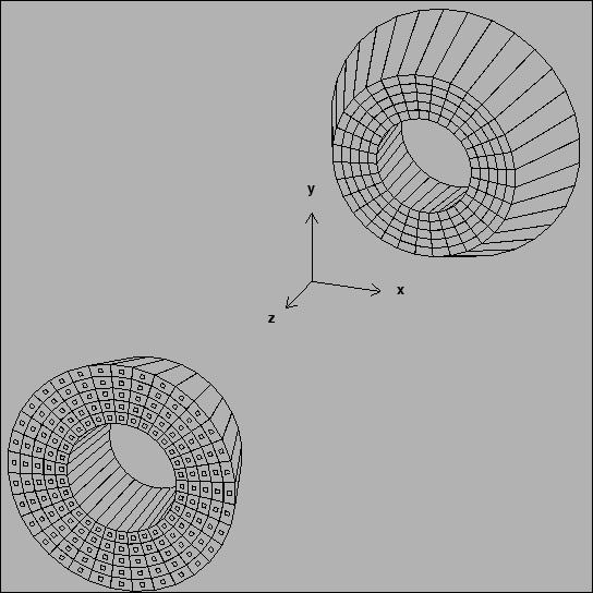
view of the crystal arrangement is shown in
Fig.
 ![[*]](./icons/crossref.png) .
.
Figure:
An isometric view of the BGO crystals of the forward and
backward EFC detectors.
 |
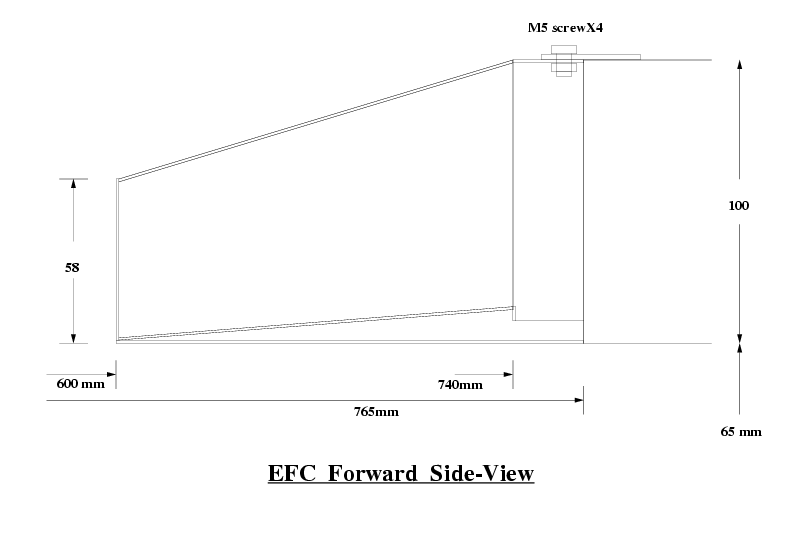
The schematic side view of the forward EFC is shown in
Fig. ![[*]](./icons/crossref.png) . The distance between the front surface of
the detector and the interaction point is 60 and 43.5 cm in the
forward and backward EFCs, respectively. The inner bore radius of the
detector is 6.5 cm.
. The distance between the front surface of
the detector and the interaction point is 60 and 43.5 cm in the
forward and backward EFCs, respectively. The inner bore radius of the
detector is 6.5 cm.
Figure:
Side view of the mounting of forward EFC.

|
The BGO crystals are housed in a bucket-shape container made of 1
mm-thick stainless steel, the inner bore of which is the beam pipe.
The container is attached to the front surface of the compensation
solenoids. Since the space allocated for EFC is limited, the radiation
lengths of the forward and backward crystals are 12 and 11,
respectively. Front-end circuits for photodiodes and preamps as well
as miscellaneous instruments are installed in the space between the
magnet surface and the backend of the BGO crystals which is 2.7 and
2.0 cm for the forward and backward EFC detectors, respectively.


Next: Light collection
Up: Design and Construction
Previous: BGO and radiation hardness
Contents
Samo Stanic
2001-06-02
