

Next: Beam-line Magnets near the
Up: Interaction Region
Previous: Interaction Region
Contents
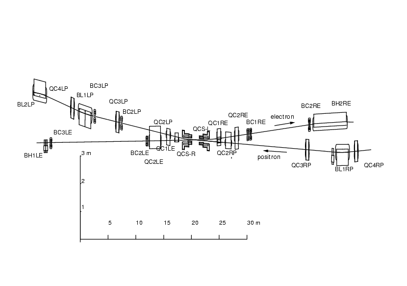
The layout of the interaction region is shown in Fig.
![[*]](./icons/crossref.png) [4]. The beam crossing angle of
[4]. The beam crossing angle of  11 mr allows us to fill all RF buckets with the beam and still
avoid parasitic collisions, thus permitting higher luminosity. Another
important merit of the large crossing-angle scheme is that it
eliminates the need for the separation-bend magnets, significantly
reducing beam-related backgrounds in the detector. The risk
associated with this choice of a non-zero crossing angle is the
possibility of luminosity loss caused by the excitation of
synchro-beta resonances [5].
Figure:
Layout of the interaction region for the beam crossing angle
of  11 mr.
 |
The low energy beam line ( ) is aligned with the axis of
the detector solenoid since the lower-momentum beam particles would
suffer more bending in the solenoid field if they were off-axis. This
results in a 22 mr angle between the high energy beam line (
 ) and
the solenoid axis.
Samo Stanic
2001-06-02
