

Next: Gas
Up: Design and Construction of
Previous: Design and Construction of
Contents
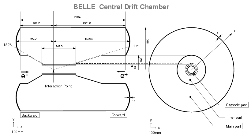
The structure of CDC is shown in Fig.
![[*]](./icons/crossref.png) . It is asymmetric in the
. It is asymmetric in the  direction in
order to provide an angular coverage of
 .
The longest wires are 2400 mm long. The inner radius is extended down
to 103.5 mm without any walls in order to obtain good tracking
efficiency for low-
 tracks by minimizing the material
thickness. The outer radius is 874 mm. The forward and backward
small-
 regions have conical shapes in order to clear the
accelerator components while maximizing the acceptance.
The chamber has 50 cylindrical layers, each containing between three
and six either axial or small-angle-stereo layers, and three cathode
strip layers.
Table ![[*]](./icons/crossref.png) gives the detailed parameters of the wire
configuration. CDC has a total of 8400 drift cells. We chose three
layers each for the two innermost stereo super-layers and four layers
each for the three outer stereo super-layers in order to provide a
highly-efficient fast
gives the detailed parameters of the wire
configuration. CDC has a total of 8400 drift cells. We chose three
layers each for the two innermost stereo super-layers and four layers
each for the three outer stereo super-layers in order to provide a
highly-efficient fast  -trigger combined with the cathode strips. We
determined the stereo angles in each stereo super-layer by maximizing
the
  -measurement capability while keeping the gain variations along
the wire below 10 %.
Figure:
Overview of the CDC structure. The lengths in the figure are
in units of mm.

|
Table:
Configurations of the CDC sense wires and cathode strips.
| Superlayer |
No. of |
Signal channels |
Radius |
Stereo angle (mrad) |
| type and No. |
layers |
per layer |
(mm) |
and strip pitch (mm) |
| Cathode |
1 |
64 (z)  8 ( 8 ( ) ) |
83.0 |
(8.2) |
| Axial 1 |
2 |
64 |
88.0  98.0 98.0 |
0. |
| Cathode |
1 |
80 (z)  8 ( 8 ( ) ) |
103.0 |
(8.2) |
| Cathode |
1 |
80 (z)  8 ( 8 ( ) ) |
103.5 |
(8.2) |
| Axial 1 |
4 |
64 |
108.5  159.5 159.5 |
0. |
| Stereo 2 |
3 |
80 |
178.5  209.5 209.5 |
71.46  73.75 73.75 |
| Axial 3 |
6 |
96 |
224.5  304.0 304.0 |
0. |
| Stereo 4 |
3 |
128 |
322.5  353.5 353.5 |
-42.28  -45.80 -45.80 |
| Axial 5 |
5 |
144 |
368.5  431.5 431.5 |
0. |
| Stereo 6 |
4 |
160 |
450.5  497.5 497.5 |
45.11  49.36 49.36 |
| Axial 7 |
5 |
192 |
512.5  575.5 575.5 |
0. |
| Stereo 8 |
4 |
208 |
594.5  641.5 641.5 |
-52.68  -57.01 -57.01 |
| Axial 9 |
5 |
240 |
656.5  719.5 719.5 |
0. |
| Stereo 10 |
4 |
256 |
738.5  785.5 785.5 |
62.10  67.09 67.09 |
| Axial 11 |
5 |
288 |
800.5  863.0 863.0 |
0. |
The individual drift cells are nearly square and, except for the inner
three layers, have a maximum drift distance between 8 and 10 mm and a
radial thickness that ranges from 15.5 to 17 mm. The drift cells in
the inner layers are smaller than the others and their signals are
read out by cathode strips on the cylinder walls. These cell
dimensions were optimized based on the results of beam test
measurements [32].
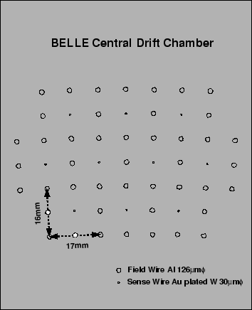
Fig. ![[*]](./icons/crossref.png) shows the cell arrangement in which the
neighboring radial layers in a superlayer are staggered in
shows the cell arrangement in which the
neighboring radial layers in a superlayer are staggered in  by a
half cell to resolve left-right ambiguities. The sense wires are gold
plated tungsten wires of 30
  m in diameter to maximize the drift
electric field. The field wires of unplated aluminum of 126
  m in
diameter are arranged to produce high electric fields up to the edge
of the cell and also to simplify the drift time-to-distance relation.
The aluminum field wires are used to reduce the material of the
chamber. The electric field strength at the surface of the aluminum
field wires is always less than 20 kV/cm, a necessary condition for
avoiding radiation damage [33].
Figure:
Cell structure of CDC.
 |
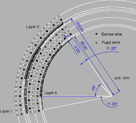
Three  -coordinate measurements at the inner-most radii are provided
by cathode strips as shown in
Fig.
 ![[*]](./icons/crossref.png) [34]. They were glued on
the inner cylinder surface of the chamber and on both sides of a 400
[34]. They were glued on
the inner cylinder surface of the chamber and on both sides of a 400
 m thick CFRP cylinder located between the second and third anode
layers. In order to maintain the mechanical strength and accuracy,
aluminum guard rings were attached on the both ends with electrically
conducting glue. The deviation from a perfect cylindrical shape is
less than 100
  m in radius. The cathode strips are divided into
eight segments in the
  direction and have an 8.2 mm pitch in the
 direction. The strip width is 7.4 mm. The total number of cathode
channels is 1,792. The deterioration of the momentum resolution due
to multiple scattering in the cathode materials is minimized.
Figure:
Cell structure and the cathode sector configuration.
 |
The total wire tension of 3.5 tons is supported by the aluminum
end-plates and the CFRP cylinder structures that extend between the
end-plates. Each end plate consists of three parts; the cathode,
inner and main parts as indicated in
Fig. ![[*]](./icons/crossref.png) . The cathode part of a 16 mm thick flat
plate corresponds to the three innermost anode layers and three
cathode layers. The conically-shaped inner part covers 11 anode layers
in the radial range from 103.5 to 294 mm. The end-plate thickness in
the
. The cathode part of a 16 mm thick flat
plate corresponds to the three innermost anode layers and three
cathode layers. The conically-shaped inner part covers 11 anode layers
in the radial range from 103.5 to 294 mm. The end-plate thickness in
the  direction is 11
  18 mm for the backward side and 25
 31 mm for the forward side. The end-plate of the main part is
10 mm in thickness and has a curved profile to minimize distortions
caused by the wire tension. The three end-plate parts are connected to
each other by stainless steel bolts and gas sealed with silicone glue.
The 754.5 mm radial space between the 3rd and 50th anode layers
contains only gases and wires.
The feed-through holes were drilled by a custom designed drilling
machine at the KEK machine shop. The hole position accuracy is better
than 30  m.
m.


Next: Gas
Up: Design and Construction of
Previous: Design and Construction of
Contents
Samo Stanic
2001-06-02
