

Next: Cathode strip detector
Up: Calibration with Cosmic Rays
Previous: Calibration with Cosmic Rays
Contents
Cosmic ray data were taken with the solenoid operating at its nominal
1.5 T field. A positive high voltage was applied to the sense wires,
and the field wires were connected to the end-plates and kept at
ground. The sense wire high voltages, typically 2.35 kV, were
adjusted layer-by-layer to keep the same gas gain (several  ) for different cell sizes. The chamber was operated at a
constant pressure slightly above one atmosphere.
The standard trigger and data acquisition system developed for
operation in the Belle experiment was used in the cosmic ray run.
Back-to-back cosmic ray events were triggered by the Belle TOF counter
system [40].
The event timing was determined with a 0.7 ns resolution using TOF
information. The acceptance for cosmic ray tracks was determined by
TOF which has a smaller polar angle acceptance than CDC.
We accumulated a sample of  cosmic ray tracks. After
requiring tracks to go through the interaction region (
 cm
cm
 cm and
  cm), 56,743 events remain, where
 is the closest distance in the
  -
- plane and
  is the
closest distance in the
  coordinate.
Extensive works on the optimization of the drift-time versus distance
function were carried out by minimizing residual distributions for the
function iteratively. Separate functions were used for each layer and
each incident angle of the track with respect to the radial direction.
A correction for the signal propagation time along the wire was
applied after the first 3-D track reconstruction. Corrections were
also made for the effects of wire sag and distortions of the
end-plates caused by the wire tension by using the measured data. The
relative alignment of the cathode and inner end-plates with respect to
the main end-plates was determined using cosmic ray data. The
rotations and translations thus acquired were found to be less than
200  m, consistent with the estimated construction accuracy.
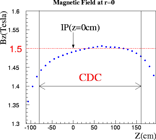
Figure ![[*]](./icons/crossref.png) shows the
shows the  dependence of
  , the
axial component of the magnetic field, measured before the
installation of CDC. The non-uniformity of the magnetic field is as
large as 4 % along the central axis. The Kalman filtering
method [41] was used to correct the effects due to the
non-uniformity of the measured magnetic field.
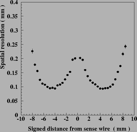
Fig.
 ![[*]](./icons/crossref.png) shows the spatial resolution as a
function of the drift distance. Near the sense wire and near the cell
boundary the spatial resolution is significantly poorer. The spatial
resolution for tracks passing near the middle of the drift space is
approximately 100
shows the spatial resolution as a
function of the drift distance. Near the sense wire and near the cell
boundary the spatial resolution is significantly poorer. The spatial
resolution for tracks passing near the middle of the drift space is
approximately 100  m.
m.
Figure:
Measured axial component of the magnetic field produced by
the Belle solenoid. The nominal value of the magnetic field inside
CDC is 1.5 T. The difference between the minimum and maximum values
along the central axis is about 4 %.
 |
Figure:
Spatial resolution as a function of the drift distance.
 |
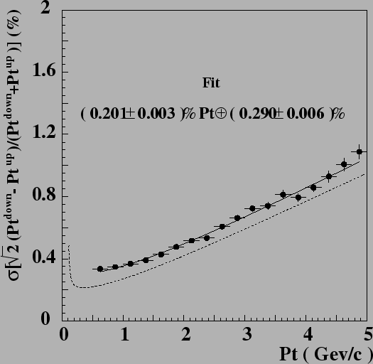
The  resolution as a function of
  is shown in
Fig.
 ![[*]](./icons/crossref.png) . The solid curve indicates the result
fitted to the data points, i.e.
. The solid curve indicates the result
fitted to the data points, i.e.
 in % (
 in GeV/c). The dashed curve shows the
ideal expectation for
  particles, i.e.
 in %. No apparent systematic effects due to the particle
charge were observed.
Figure:
 dependence of
  resolution for cosmic rays. The
solid curve shows the fitted result (0.201 %
  0.290
%/
 ) and the dotted curve (0.118 %
  0.195 %)
shows the ideal expectation for
  = 1 particles .
 |


Next: Cathode strip detector
Up: Calibration with Cosmic Rays
Previous: Calibration with Cosmic Rays
Contents
Samo Stanic
2001-06-02


