

Next: Beam Background
Up: Interaction Region
Previous: Beam-line Magnets near the
Contents
The precise determination of decay vertices is an essential feature of
the Belle experiment. Multiple coulomb scattering in the beam-pipe
wall and the first layer of the silicon detector are the limiting
factors on the  -vertex position resolution, making the minimization
of the beam-pipe thickness a necessity. Moreover, since the vertex
resolution improves inversely with the distance to the first detection
layer, the vertex detector has to be placed as close to the
interaction point as possible and, thus, to the beam pipe wall. This
is complicated by the fact that the beam pipe at the interaction
region is subjected to beam-induced heating at levels as high as a few
hundred watts. This requires an active cooling system for the beam
pipe and a mechanism for shielding the vertex detector from this
heat.
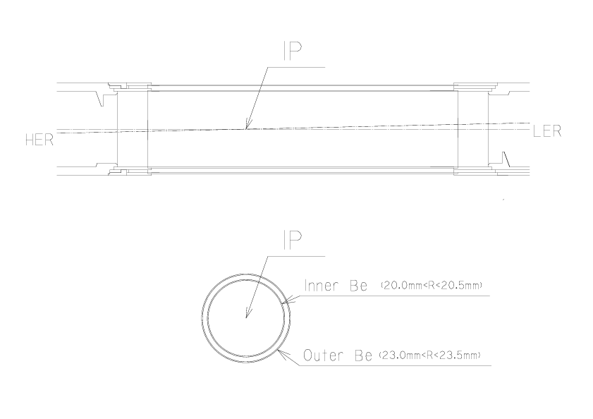
Figure ![[*]](./icons/crossref.png) shows the cross section of the beryllium
beam pipe at the interaction point. The central part (-4.6 cm
shows the cross section of the beryllium
beam pipe at the interaction point. The central part (-4.6 cm  10.1 cm) of the beam pipe is a double-wall beryllium cylinder
with an inner diameter of 40 mm. A 2.5 mm gap between the inner and
outer walls of the cylinder provides a helium gas channel for cooling.
The machine vacuum is supported by the 0.5 mm thick inner wall. The
outer wall is also 0.5 mm thick. The beryllium central section is
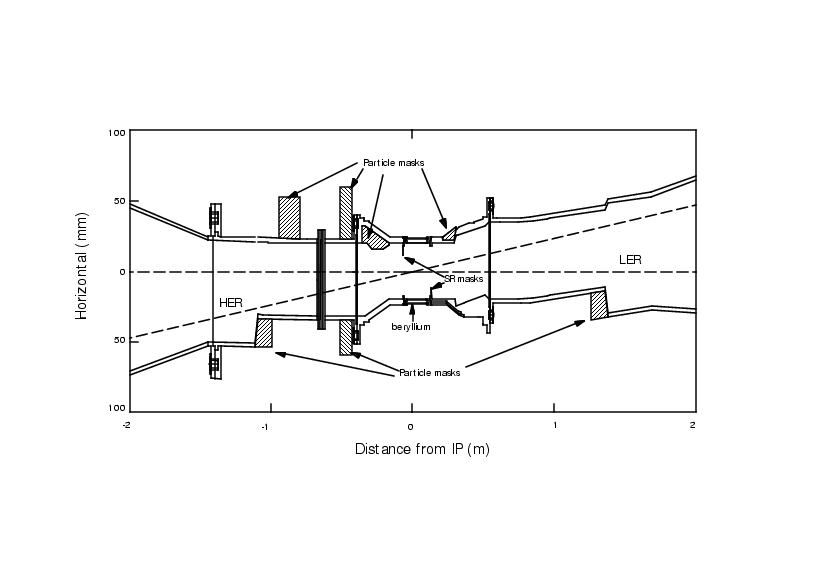
brazed to aluminum pipes that extend outside of the collision region
as shown in
Fig.
 ![[*]](./icons/crossref.png) . The conical shape of the aluminum beam pipe
allows the synchrotron x-rays generated in the QCS and QC1 magnets to
pass through the detector region without hitting the beam pipe wall.
The helium-gas cooling is adopted instead of water in order to
minimize the material in the beam pipe.
. The conical shape of the aluminum beam pipe
allows the synchrotron x-rays generated in the QCS and QC1 magnets to
pass through the detector region without hitting the beam pipe wall.
The helium-gas cooling is adopted instead of water in order to
minimize the material in the beam pipe.
Figure:
The cross section of the beryllium beam pipe at the
interaction point.

|
Figure:
The arrangement of the beam pipe and horizontal masks.

|
Assuming a uniformly distributed 100 W heat load on the inner wall,
the maximum temperature increase for the inner (outer) beryllium wall
is calculated to be 25 (5)  C for a 2 g/s He flow velocity at a 1.5
atm pressure and a 0.0007 atm pressure drop. The calculation assumes
that the aluminum tubes in contact with the ends of the beryllium
section are maintained at a fixed temperature by an independent
cooling system. The total material thickness of the central beryllium
section is 0.3 % of a radiation length. Outside the outer beryllium
cylinder, a 20
  m thick gold sheet is attached in order to reduce
the low energy x-ray background (
 5 keV) from the high energy ring.
Its thickness corresponds to 0.6 % of a radiation length.


Next: Beam Background
Up: Interaction Region
Previous: Beam-line Magnets near the
Contents
Samo Stanic
2001-06-02
