

Next: Trigger Timing Modules
Up: Back-end Electronics
Previous: Back-end Electronics
Contents
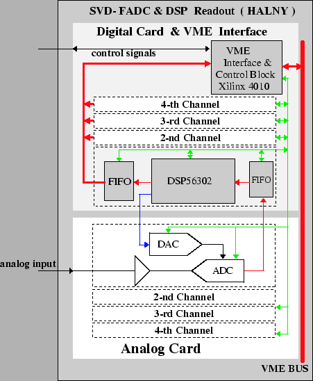
Figure ![[*]](./icons/crossref.png) shows the block diagram of the FADC module,
which is called ``Halny
shows the block diagram of the FADC module,
which is called ``Halny![[*]](./icons/footnote.png) ''. Each ``Halny'' module incorporates four
channels of FADC, FIFO buffering, and Motorola DSP56302 digital signal
processor. The DSPs carry out the pedestal subtraction and zero
suppression calculations on a channel-by-channel basis and implement
low-level data formatting. The DSPs also calculate pedestals and hit
thresholds using a dynamic algorithm that automatically adjusts for
pedestal shifts and changes in noise level.
''. Each ``Halny'' module incorporates four
channels of FADC, FIFO buffering, and Motorola DSP56302 digital signal
processor. The DSPs carry out the pedestal subtraction and zero
suppression calculations on a channel-by-channel basis and implement
low-level data formatting. The DSPs also calculate pedestals and hit
thresholds using a dynamic algorithm that automatically adjusts for
pedestal shifts and changes in noise level.
Figure:
Block diagram of a  FADC module.
 |
Samo Stanic
2001-06-02
