

Next: Monitor System
Up: Silicon Vertex Detector, SVD
Previous: Trigger Timing Modules
Contents
The SVD DAQ system consists of a data manager, a run manager and an
interlock. The data manager transfers data from the FADC output FIFOs
to the central event builder and the run manager controls the DAQ
hardware. The interlock monitors running conditions and sends signals
to the run manager when an abnormal state is detected.
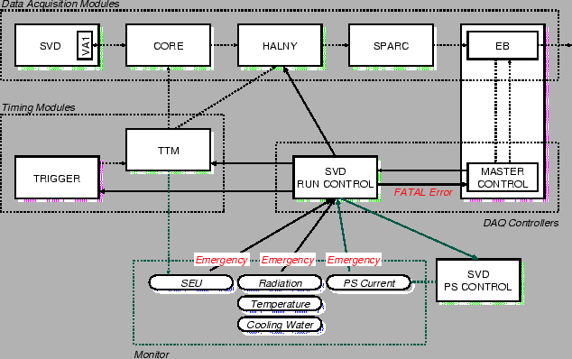
Fig. ![[*]](./icons/crossref.png) shows a block diagram of the data acquisition
and the monitoring system for SVD. The SVD back-end electronics
system comprises a TTM system in a VME crate and four FADC VME
systems. An FADC system consists of eight FADC modules and a SPARC
VME module. The VME modules (TDM, TTMs and HALNYs) are controlled by
a VME master module (i.e. a SPARC VME module) in each VME crate.
shows a block diagram of the data acquisition
and the monitoring system for SVD. The SVD back-end electronics
system comprises a TTM system in a VME crate and four FADC VME
systems. An FADC system consists of eight FADC modules and a SPARC
VME module. The VME modules (TDM, TTMs and HALNYs) are controlled by
a VME master module (i.e. a SPARC VME module) in each VME crate.
Figure:
Block diagram of the SVD DAQ system.
 |
The four FADC subsystems collect and transmit data to the event
builder in parallel. SPARC VME boards resident in each of the four
FADC crates carry out this task. The SPARC VME boards poll the status
of each HALNY board in its crate and waits for a response indicating
that a digitized event is ready to be read. HALNY data is transferred
from the output FIFOs on a word-by-word basis.
The SVD run manager controls DAQ VME modules (TDM, TTMs and HALNYs).
It initiates or terminates trigger sequences, downloads firmware to
the TTMs and Halnys, and issues resets at the beginning of each run
and when requested by CDAQ. It also controls the run mode of the VA1
and CORE front-end electronics, via TTMs. Finally, it initiates
recovery procedures upon request from the interlock.
The SVD interlock system monitors running conditions of SVD. The data
integrity is checked by the consistency of the event size and
begin/end event markers. The condition of VA1s is monitored by
checking the digital outputs from the hybrids and by tracking their
power-supply currents. Temperatures of the hybrids, heat-sinks and
end-rings, and water circulation are monitored to make sure that the
cooling system is in working order. The beam abort signal from the
radiation monitor described below is also fed into the interlock.
When the system senses a fault condition on one of its inputs, it
shuts down the power supplies for the front-end electronics and sends
an abort signal to the run manager.


Next: Monitor System
Up: Silicon Vertex Detector, SVD
Previous: Trigger Timing Modules
Contents
Samo Stanic
2001-06-02
