

Next: End-cap modules
Up: Design and Construction
Previous: Glass Resistive Plate Counters
Contents
There are minor differences between the barrel and the end-cap modules.
The barrel resistive plate counters which were constructed in the
United States consist of two parallel sheets of 2.4 mm-thick
commercially available float glass, the content of which is 73 %
silicon dioxide, 14 % sodium oxide, 9 % calcium oxide, and 4 %
trace elements. The bulk resistivity of the glass is -
 cm at room temperature. The plates are separated
by 1.9 mm thick extruded noryl spacers epoxied to both plates using 3M
2216 epoxi.
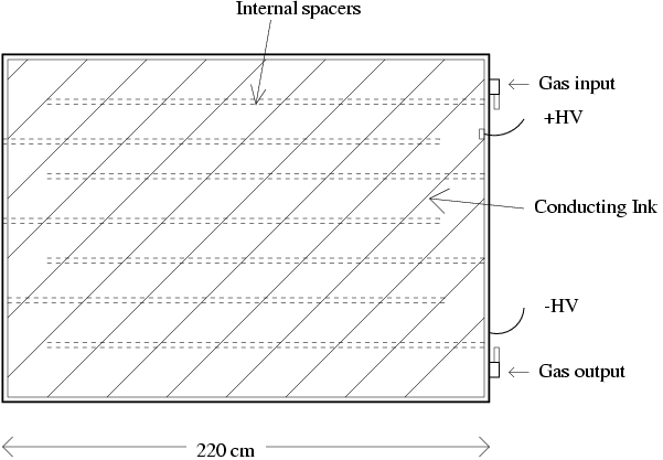
Fig.
 ![[*]](./icons/crossref.png) shows a barrel RPC with the spacers placed
every 10 cm so that they channel the gas flow through the RPC to
provide uniform gas composition throughout the active volume. A
T-shaped noryl spacer was epoxied around the perimeter forming a gas
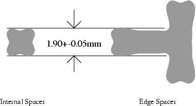
tight unit. The spacers have the cross sections shown in
Fig.
shows a barrel RPC with the spacers placed
every 10 cm so that they channel the gas flow through the RPC to
provide uniform gas composition throughout the active volume. A
T-shaped noryl spacer was epoxied around the perimeter forming a gas
tight unit. The spacers have the cross sections shown in
Fig. ![[*]](./icons/crossref.png) . They were designed with concave
regions for the epoxy joints and were extruded to an accuracy of
. They were designed with concave
regions for the epoxy joints and were extruded to an accuracy of  0.05 mm. Tilting table tops were used to lift the RCPs into the
vertical orientation to avoid flexing the epoxy joints. After
assembly, the RCPs were always moved in the vertical orientation or
supported by a rigid flat surface. The barrel RPCs are rectangular in
shape and vary in size 2.2 x 1.5 m
 to 2.2 x 2.7 m
 .
.
Figure:
Schematic diagram of the internal spacer arrangement for barrel RPC.

|
Figure:
Cross section of the internal spacer and edge in KLM.

|
To distribute the high voltage on the glass, the outer surface was
coated with Koh-i-noor 3080F india ink. The ink was mixed 30 % black
and 70 % white by weight to achieve a surface resistivity of -
 /square. This resistivity is chosen so that this
surface does not shield the discharge signal from the external pickup
pads but is small compared to the resistivity of the glass to provide
a uniform potential across the entire surface.
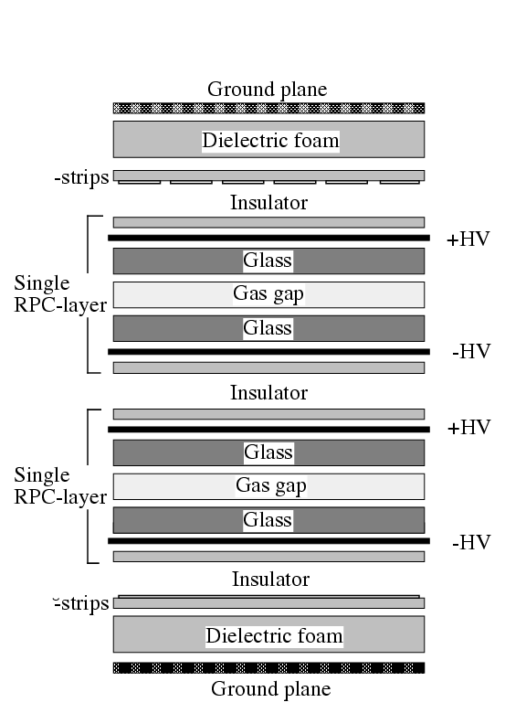
Figure ![[*]](./icons/crossref.png) shows the cross section of a
super-layer, in which two RPCs are sandwiched between the orthogonal
shows the cross section of a
super-layer, in which two RPCs are sandwiched between the orthogonal
 and
and  pickup-strips with the ground planes for signal
reference and proper impedance. This unit structure of two RPCs and
two readout-planes is enclosed in an aluminum box and is less than 3.7
cm thick. Each RPC is electrically insulated with a double layer of
0.125 mm thick mylar. Signals from both RPCs are picked up by copper
strips above and below the pair of RPCs, providing a three-dimensional
space point for particle tracking. Multiple scattering of particles as
they travel through the iron is typically a few centimeters. This
sets the scale for the desired spatial resolution of KLM. The pickup
strips in the barrel vary in width from layer to layer but are
approximately 50 mm wide with lengths from 1.5 to 2.7 m. The geometry
of the pickup strips was chosen so that the pickup strip behaves as a
transmission line with a characteristic impedance of
  50
50
 to minimize signal reflections at the junction with the
twisted-pair readout cable. The barrel modules have a 100
  resistor connecting the pickup strip to ground at the cable end of the
pickup strip to create an effective impedance of 50
  at that
point. This reduces the size of the signal which reaches the readout
boards for the barrel modules by a factor of two.
Figure:
Cross section of a KLM super-layer.

|
The double-gap design provides redundancy and results in high
super-layer efficiency of 98 %, despite the relatively low
single-layer RPC efficiency of 90 % to 95 %. In particular, the
effects of dead regions near the spacers are minimized by offsetting
their locations for the two RPCs that comprise a super-layer. To
provide overall operational redundancy, care is taken to supply gas
and HV independently for each RPC layer so that the super-layer can
continue to operate even if a problem develops with one RPC.
Each barrel module has two rectangular RPCs with 48  pickup strips
perpendicular to the beam direction. The smaller 7 super-layers closest
to the interaction point have 36
  strips and the outer 8
super-layers have 48
  strips orthogonal to the
  strips. The
backward region of the upper octant has modules that are 63 cm shorter
than the modules in the other octants in order to accommodate plumbing
for the cooling of the superconducting solenoid. This chimney region
can be seen in
Fig.
 ![[*]](./icons/crossref.png) . This amounts to less than 2 % of the solid
angle of the barrel coverage and has a minimal effect on the
acceptance since it is in the backward hemisphere.
. This amounts to less than 2 % of the solid
angle of the barrel coverage and has a minimal effect on the
acceptance since it is in the backward hemisphere.
The glass RPCs are relatively robust except for overpressure
situations which can push the two sheets of glass apart, breaking the
glass-spacer epoxy joint. To avoid this hazard, the gas volume was
not sealed during shipping. Relief bubblers protect the RPCs during
operation. The RPCs were checked for gas leaks prior to installation.
The sensitivity of our measurement was about 0.05 cc/min and this was
the leak rate limit we set for all installed RPCs.


Next: End-cap modules
Up: Design and Construction
Previous: Glass Resistive Plate Counters
Contents
Samo Stanic
2001-06-02
