

Next: Readout Electronics
Up: Design and Construction
Previous: High voltage system
Contents
We have investigated gas mixtures in search of an environmentally
friendly and non-combustible mixture that provides high detection
efficiency and stable RPC operation [76]. We compared
16 different mixtures with butane concentrations of 4, 8, 12, and 25
% and argon concentrations of 20, 25, 30, and 35 % with the balance
of the gas being HFC-134a. The RPC performance in terms of efficiency,
dark current, singles rate, and timing resolution was compared at an
operating point 200 V/mm above the knee of the efficiency plateau
curve. The butane reduces the presence of after-pulses by absorbing
photons from the initial discharge. The non-flammable limit for the
butane is about 12 % at the mixing ratio of 1:1 for the argon and
HFC-134a. We found very little difference between flammable and
non-flammable mixtures and have chosen a non-combustible mixture of 62
% HFC-134a, 30 % argon, and 8 % butane-silver.
Table ![[*]](./icons/crossref.png) lists some basic physical parameters of these
gases. Butane-silver is a mixture of approximately 70 % n-butane and
30 % iso-butane. The cost of butane-silver is one tenth of the cost
of 99.5 % pure iso-butane.
lists some basic physical parameters of these
gases. Butane-silver is a mixture of approximately 70 % n-butane and
30 % iso-butane. The cost of butane-silver is one tenth of the cost
of 99.5 % pure iso-butane.
Table:
Physical parameters of the gases used in KLM.
| Gas |
Symbol |
Mol. weight |
Density (g/ ) ) |
| Argon |
Ar |
39.95 |
1.784 (0  C, 1atm) C, 1atm) |
| Butane-silver |
C H H |
58.12 |
2.6 (0  C, 1atm) C, 1atm) |
| HFC-134a |
CH FCF FCF |
102.0 |
4.5 |
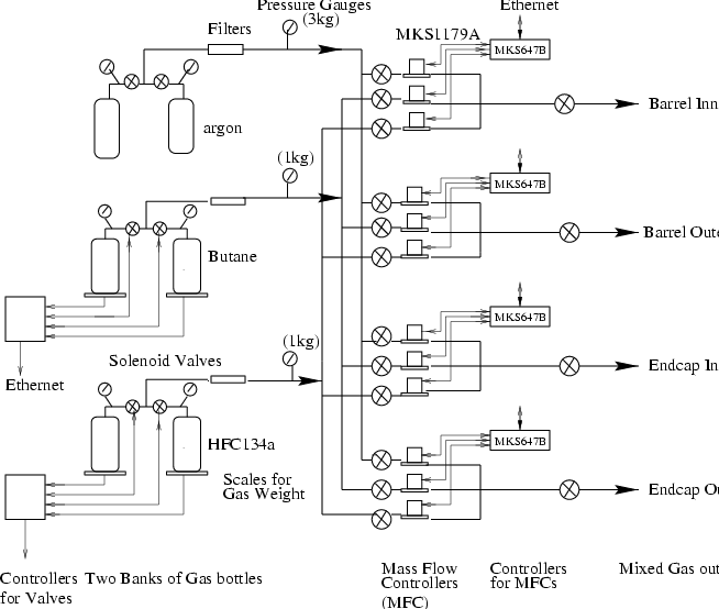
Two separate banks of bottles are arranged for each type of gas. When
one side becomes empty, the supply line automatically switches to the
other. Tank quantities are measured by weight for butane and HFC-134a
and by pressure for argon. A diagram of the mixing system is shown in
Fig. ![[*]](./icons/crossref.png) . The three gases are sent to MKS model
1179A mass flow controllers for mixing in the appropriate ratios.
Four gas mixing systems are used separately for the inner RPCs in the
barrel super-layers, the barrel outer RPCs, the end-cap inner RPCs, and
the end-cap outer RPCs. The flow rates from the mass flow controllers
are monitored via a network connection and the high voltage is
automatically lowered if a deviation from the desired flow rate is
detected. During normal operation, we flow a total of 4.5
. The three gases are sent to MKS model
1179A mass flow controllers for mixing in the appropriate ratios.
Four gas mixing systems are used separately for the inner RPCs in the
barrel super-layers, the barrel outer RPCs, the end-cap inner RPCs, and
the end-cap outer RPCs. The flow rates from the mass flow controllers
are monitored via a network connection and the high voltage is
automatically lowered if a deviation from the desired flow rate is
detected. During normal operation, we flow a total of 4.5  /min,
which corresponds to approximately one volume change per day.
Figure:
KLM gas mixing system.

|
The gas distribution system is designed to provide an independent gas
supply to each RPC in a super-layer. Therefore, if one supply line
fails for any reason, the other RPC in the same super-layer will still
be operational. To ensure uniform distribution of the flow without
the need for tedious adjustments, a "flow resistor" was inserted in
series upstream of each RPC. These devices are 10 cm-long
stainless-steel tubes with an inner diameter of 254  m. The flow
impedance of the tubes is about ten times larger than that of an RPC
layer. Thus the flow rate is determined by the flow resistor (uniform
to about 15 %) and almost independent of variations in the flow
resistance of individual RPCs.
The exhaust system has an active control of the exhaust pressure and
relief bubblers at various points in the system to prevent any
overpressure situations. Tests indicated that epoxy joints between
the glass plates and the internal spacers begin to detach when a
barrel RPC is pressurized above 50 mmAq. For safety reasons, the
exhaust gas is dumped outside the experimental hall through a 20 m
vertical exhaust line. Due to the large density of the mixed gas a
suction pump system is used.


Next: Readout Electronics
Up: Design and Construction
Previous: High voltage system
Contents
Samo Stanic
2001-06-02