


Next: Efficiency and resolution
Up: and Muon Detection System,
Previous: Gas mixing and distribution
Contents
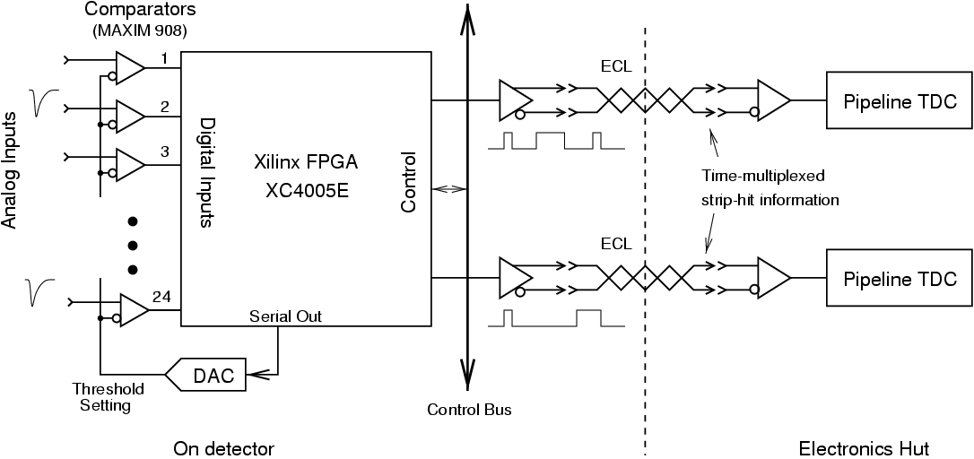
Readout of 38 k pickup strips is accomplished with the use of
custom-made VME-based discriminator/time-multiplexing boards developed
by Princeton University and Osaka City University groups. The system
consists of the signal discrimination and multiplexing boards, crate
controller boards (one per crate) for crate-wide control and data
processing, string controller boards for downloading and controlling
multiple readout crates, and FASTBUS time-to-digital converters.
The discriminator boards are 6U-size VME boards with 96 input channels
per board. A comparator (MAX908CPD) is used to generate a logic
signal if the voltage on the input channel exceeds the threshold
voltage. This threshold can be selected via a programmable
digital-to-analog converter to be any value from - 250 mV to + 250 mV.
A time multiplexer scheme combines hit information from 12 RPC
channels into a single high-speed serial data stream that is passed to
a LeCroy 1877 pipelined TDC. The multiplexing is accomplished with a
Xilinx XC4005E FGPA. A schematic diagram of the readout electronics is
shown in
Fig. ![[*]](./icons/crossref.png) . In addition, the logical OR of the hits
for each 12-channel group is generated and is available for use as a
fast trigger signal.
. In addition, the logical OR of the hits
for each 12-channel group is generated and is available for use as a
fast trigger signal.
Figure:
Schematic diagram of the KLM readout electronics.
|
Each VME crate has a crate-controller board which transmits control
data from the string controller to the discriminator boards via the
dedicated VME backplane. A 10 MHz clock signal from the
crate-controller board is distributed throughout the crate for the
discriminator boards in time sequencing the RPC hits. The string
controller is a multi-function VME-compatible board using a Xilinx 4013
programmable gate array to allow downloading and control of a string
of up to 8 RPC readout crates. Once the discriminator board is
programmed, the time sequenced hit information travels directly from
each 96 channel board to 8 TDC channels residing in a FASTBUS
crate. In this manner, 38 k RPC channels are reduced to 3200 FASTBUS
TDC channels, resulting in significant cost savings. It is also
possible to read RPC strip-hit data directly through the string
controllers, as was done during system commissioning when the
production TDC system was not yet available.
Next: Efficiency and resolution
Up: and Muon Detection System,
Previous: Gas mixing and distribution
Contents
Samo Stanic
2001-06-02