

Next: Readout electronics
Up: Design and Construction of
Previous: CsI() crystal
Contents
Each crystal is wrapped in a diffuse reflector sheet for the best
collection of scintillation light at the end of the crystal. After
testing several candidates, we have chosen a single layer of 200
 m thick Goretex teflon as the wrapping material because it gives
a good light output, is easy to handle, and is expected to be stable
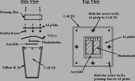
against aging. The mechanical assembly of a single CsI(
 ) counter
is shown in
Fig.
 ![[*]](./icons/crossref.png) . All sides of the crystal, except for the
end face for light readout, are covered by a single layer of 200
. All sides of the crystal, except for the
end face for light readout, are covered by a single layer of 200
 m thick porous teflon. It is then covered by a laminated sheet of
25
  m thick aluminum and 25
  m thick mylar for light and
electrical shielding. An aluminum-shielded preamplifier box is
attached on the aluminum base plate with screws.
Figure:
Mechanical assembly of the ECL counter.
 |
Two photodiodes, each having an active area of 10 mm  20 mm,
are glued at the center of crystal end surface via acrylite plate of 1
mm in thickness. The acrylite plate is used because direct glue joints
between the photodiode and the CsI were found to fail after
temperature cycling, probably due to the different thermal expansion
coefficients of silicon and CsI. ECCOBAND 24 glue from Grace Japan
Co. is used.
The barrel crystals were installed in a honeycomb-like structure
formed by 0.5 mm-thick aluminum septum walls stretched between the
inner and outer cylinders. The outer cylinder, the two end rings, and
the reinforcing bars are made of stainless steel and form a rigid
structure that supports the weight of the crystals. The inner
cylinder is made of 1.6 mm-thick aluminum to minimize the inactive
material in front of the calorimeter. Except for the barrel end,
eight crystals, four rows in  and two columns in
  , were
inserted in each cell and fixed to the reinforcing bars through a
fixing jig at the back. In each cell at the barrel end, ten crystals,
five rows in
  and two columns in
  , were inserted. The
whole barrel structure was installed in a thick stainless steel
cylinder supported from the magnet. Finite element calculations
indicate that the whole barrel structure would sag
  200
200  m in
the final assembly that is considered to be safe for the contained
crystals. The overall support structure is made gas tight and flushed
with dry air to provide a low-humidity (5 %) environment for the
CsI(
 ) crystals. The preamplifier heat, a total of 3 kW, is removed
by a liquid cooling system. An operating temperature of lower than
30
 C with
  C stability is required for the stable operation
of the electronics.
The end-cap support structure is similar to that of the barrel. Here
the crystal weight is transmitted via a front plate, thin septa, a
side wall, inner/outer walls to thick back-reinforced bars that are
supported from blocks mounted on a support cylinder. The end-cap
calorimeter can be slided out using an additional end-cap mover with
rails when access to the inner detectors is necessary.


Next: Readout electronics
Up: Design and Construction of
Previous: CsI() crystal
Contents
Samo Stanic
2001-06-02
